1. Robot Assembly
1) Assembling the Robot
- Please refer to the manual for assembling the robot.
- Ensure all components are properly connected.
2) Verifying Cable Connections
-
Left DC Motor Connected to the Left Wheel
→ Connects to the M1 Port on the CPU board. -
Right DC Motor Connected to the Right Wheel
→ Connects to the M2 Port on the CPU board. -
Servo Motor with the Rear Booster
→ Connects to the OUT1 Port on the CPU board. -
Front LED 1
→ Connects to the OUT2 Port on the CPU board.
2. Code Upload & Robot Operation
1) When using the Complete Robot Operation Program
- If the X2 Operation Program is already uploaded, to the robot, please proceed directly to Operate Robot.
① Preparing for Upload
- Ensure mBlock is installed on your computer. If not, please install mBlock.
- To operate the robot, you will need a download board and a download cable. If you do not have these components, please purchase them.
② Download and Load the Operation Program
- Please refer to the Using the Operation Program page to download the X2 Operation Program and load it into mBlock.
③ Uploading the Code
- Upload the code to the robot by following the instructions on the upload method page or video (starting at 34 seconds).
④ Operating the Robot
- ① Turn on the power to the CPU board.
- ② Press and hold the START button for more than 2 seconds. Release it when you hear the "Do Re Mi Fa Sol La Ti Do" melody.
- ③ Press the START button 4 times to select the "Fa" tone.
- ④ Turn on the power to the remote control and have fun controlling the robot.
2) If You Are Coding the Program Yourself
① Preparing for Upload
- Ensure mBlock is installed on your computer. If not, please install mBlock.
- To operate the robot, you will need a download board and a download cable. If you do not have these components, please purchase them.
② Coding the Program
- Launch mBlock and freely code your program by referring to the coding examples or the manual.
③ Uploading the Code
- Upload the code to the robot by following the instructions on the upload method page or video (starting at 34 seconds).
④ Operating the Robot
- ① Turn on the power to the CPU board.
- ② Briefly press the START button on the CPU board and then release it.
- ③ Turn on the power to the remote control and have fun controlling the robot.
3. Coding Examples
- To check the answer, swipe the image to the side.
1) Raising and Lowering the Booster
Raise the Booster
Set the servo motor angle to 5.
Select ‘OUT1’ as the port since the servo motor is connected to the OUT1 port.
Lower the Booster
Set the servo motor angle to 70.
2) Turning the LED On and Off for 1 Second
Turn On the LED
Select ‘OUT2’ as the port since ‘LED 1’ is connected to the OUT2 port.
Turn the LED On and Then Off
Turn on the LED, wait for 1 second, then turn it off.
3) Controlling the Robot with the Remote Control
When the remote control button is pressed:
- Button 5: Turn on the LED and raise the booster
- Button 6: Turn off the LED and lower the booster
The actions to be performed when a remote control button is pressed should be placed inside the “forever” block.
When the remote control button is pressed:
- Button 1: Move forward
- Button 2: Move backward
- Button 3: Turn left in place
- Button 4: Turn right in place
- Button 5: Turn on the LED and raise the booster
- Button 6: Turn off the LED and lower the booster
4. Troubleshooting Robot Issues
1) When the Power Does Not Turn On
- Ensure the batteries are inserted with the correct polarity, matching the ‘+’ and ‘-‘ signs.
- Verify that the jumper cap is properly inserted into the 12V power connector on the CPU board.
- If there is no jumper cap available, use a 3×8 bolt to connect to the 12V power connector as an alternative.
- Inspect the battery pack cable for any breaks or disconnections.
- Ensure that the battery pack cable is securely connected to the 6V power connector on the CPU board.
2) When the Remote Control is Not Working
3) When the DC Motor Does Not Rotate / Rotates in the Wrong Direction
- Ensure that the motor cables are correctly connected to the motor port.
- Check the motor cables for any signs of disconnection or damage.
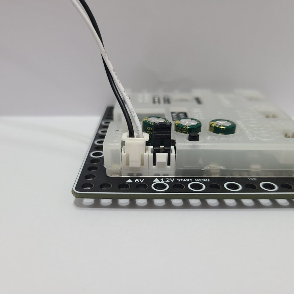
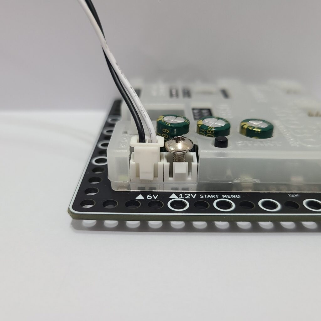
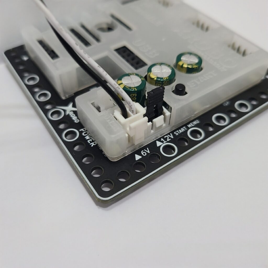
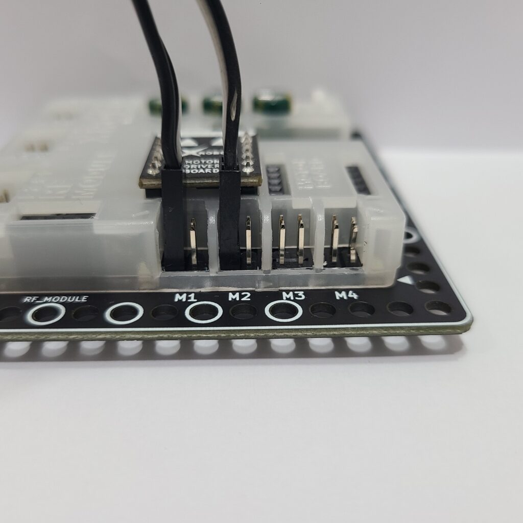
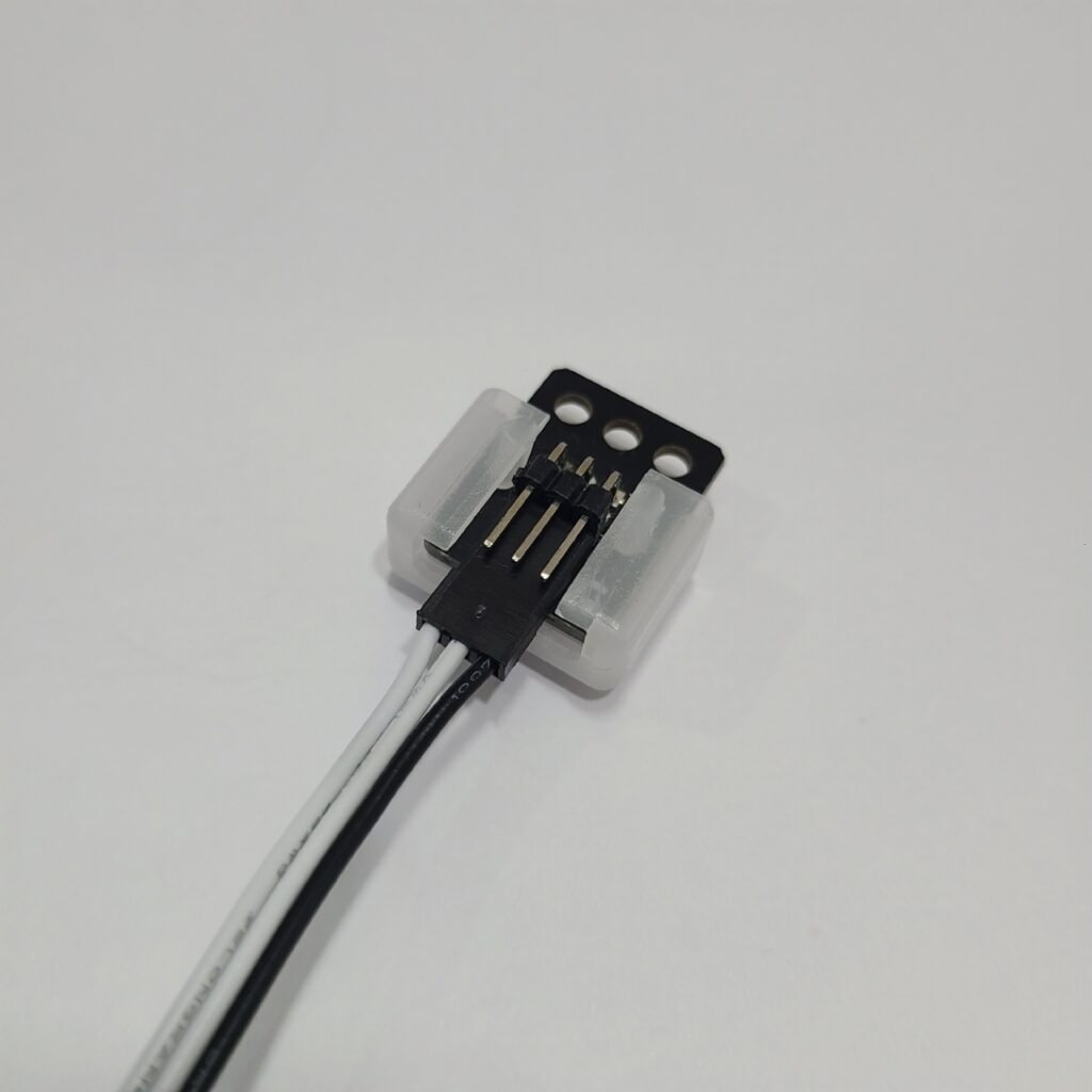
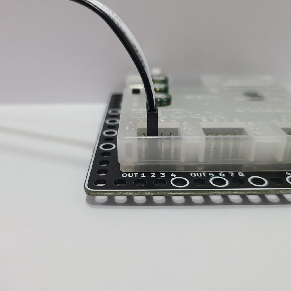
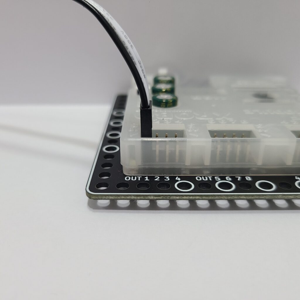
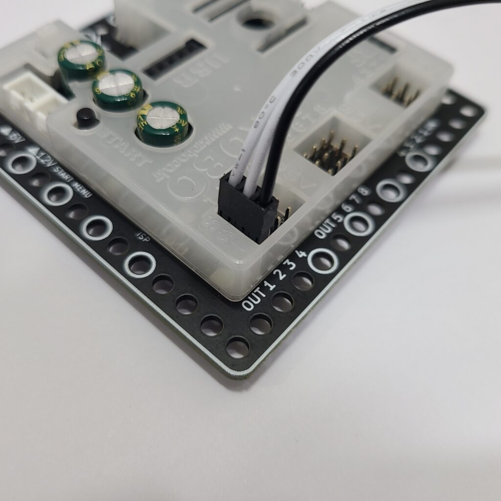
- Confirm that the motor cables are inserted vertically into the motor ports on the CPU board. If connected horizontally, the motor may not rotate.
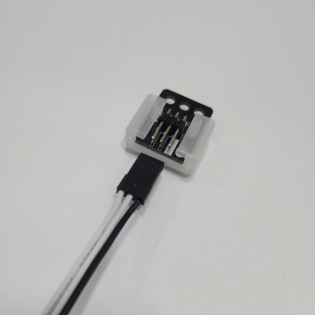
- Ensure the black wire of the motor cable is aligned with the arrow on the CPU board case. If connected in reverse, the DC motor will rotate in the opposite direction.
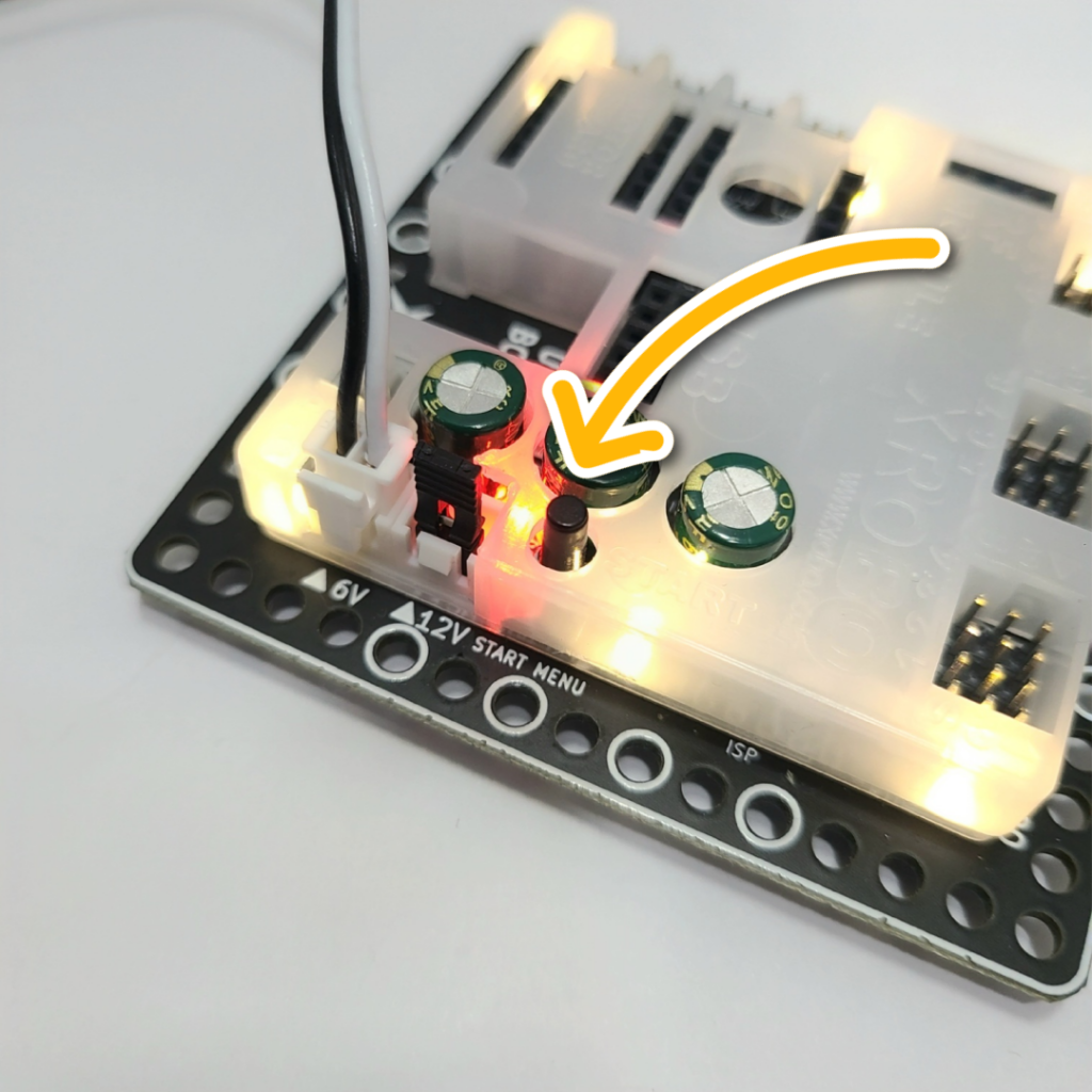
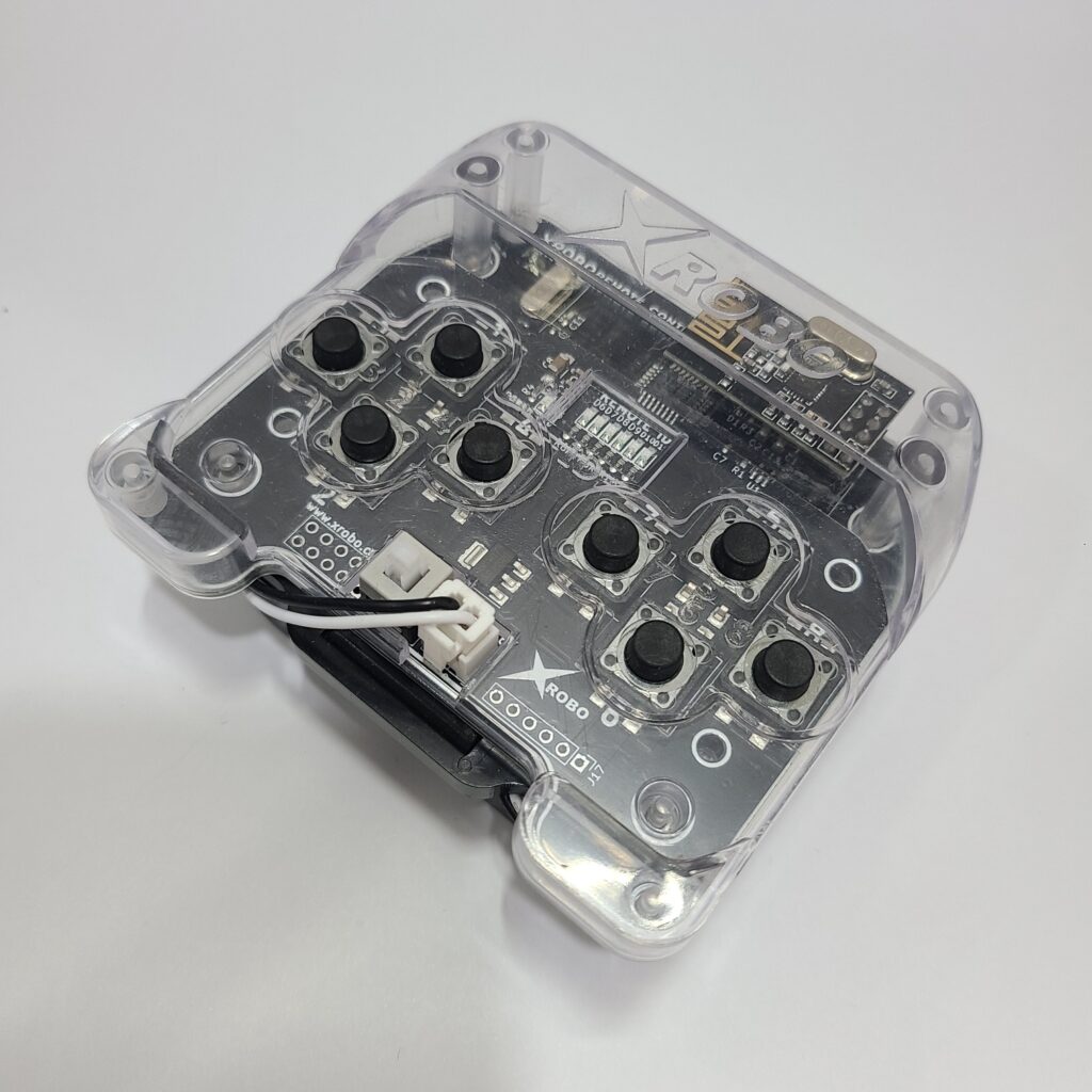
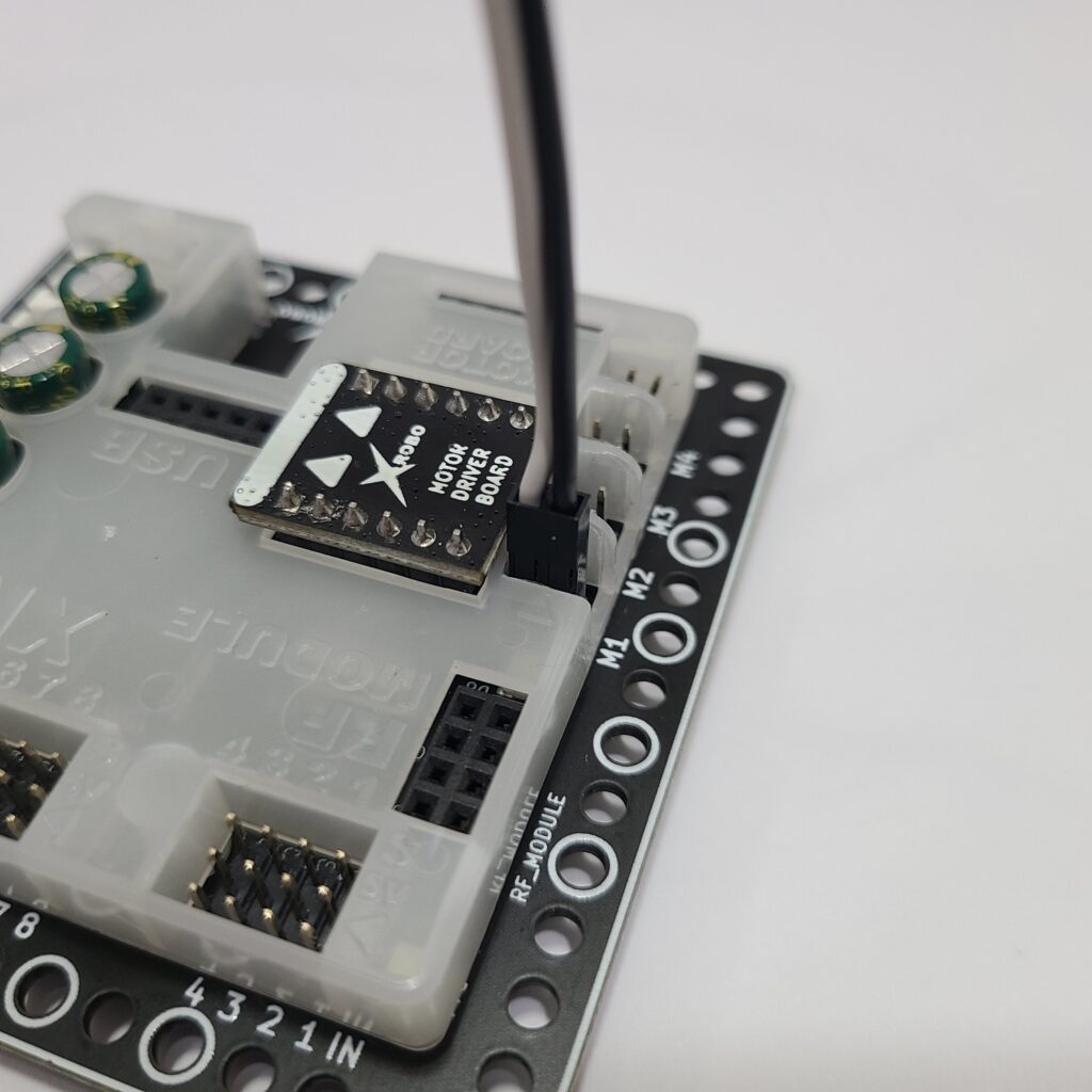
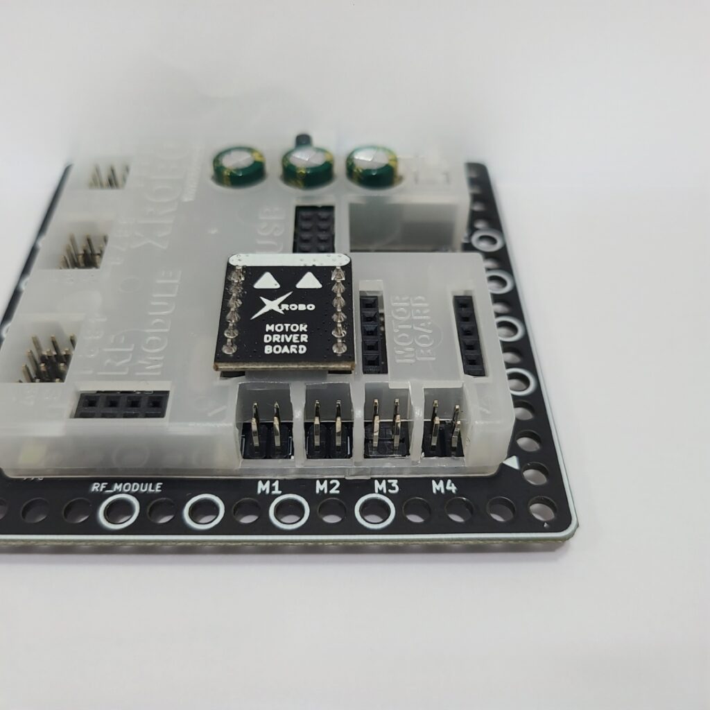
- If the DC motor driver board is not inserted according to the assembly diagram, do not turn on the power. Insert it correctly as per the assembly diagram to avoid overheating risks during operation.
- If the DC motor driver board is not inserted, place it properly and then turn on the power to check the operation.
4) When the LED is Not Functioning Properly
- Ensure that the 3-PIN cable is connected to the correct OUT port.
- Verify that the black wire of the 3-PIN cable is plugged into the side of the LED pin with the white line.
- Confirm that the black wire of the 3-PIN cable is connected in the direction of the arrow on the CPU board case.
5) When the Servo Motor is Not Functioning Properly
- Ensure that the 3-PIN cable is connected to the correct OUT port.
- Verify that the black wire of the servo motor cable is plugged in the direction of the arrow on the CPU board case.
- Connect the cable so that the black wire aligns with the arrow on the CPU board.
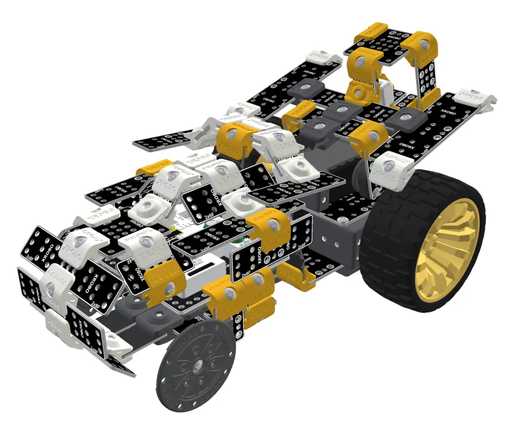
- Ensure that the direction of the servo motor label in the assembled robot matches the assembly diagram. If the label is oriented incorrectly, the servo motor may operate in reverse, or the angle may be incorrect, posing a risk of gear damage.
6) When the Robot Operates Abnormally
- Ensure that the direction of the DC motor shaft in the assembled robot matches the assembly diagram. Incorrect assembly of the motor shaft may cause the robot wheels to get stuck on the frame and malfunction.
- Check that the cables are not caught in the drivetrain. If the cables are entangled with the drivetrain, the robot may not function properly.