Components
CPU Module Kit
CPU Module Kit
CPU Board
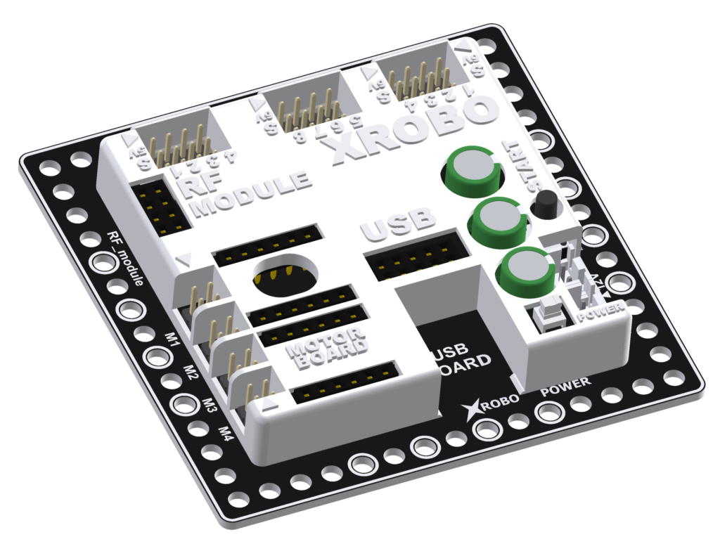
- The CPU board functions as the brain of the robot, executing code to control various hardware components.
- Using the Scratch-based mBlock block coding program, you can easily program the code.
- Connect the desired hardware to the appropriate port.
- Program the code using mBlock or Arduino.
- Upload the code to the CPU board.
- Turn on the power to the CPU board and press the Start button to execute the code.
- Voltage : 6V or 12V (AA)
- I/O Ports
- Motor Ports – 4 (can control up to 8 DC motors
- Output Ports – 8
- Input Ports – 4
- Built-in Hardware : Buzzer, LED
DC Motor Drive Board
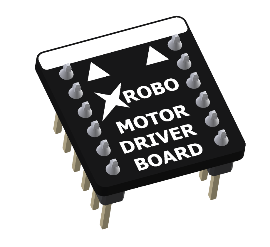
- ESSENTIAL when using DC motors
- It is hardware that assists in controlling the rotation direction and speed of the DC motors.
- When you want to use a DC motor, plug the motor drive board into the motor drive board port on the CPU board.
- Connect it to the motor port you intend to use.
- Voltage : 6V or 12V
- Output Current : 2.5A
- Driving Motors : Up to 4 motors
RF Module
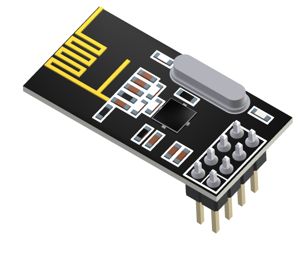
- ESSENTIAL when using a remote control.
- It enables the transmission and reception of Bluetooth signals.
- To wirelessly control the robot using the remote control transmitter, plug the RF module into the RF module port on the CPU board.
- The remote control transmitter is equipped with a built-in RF module.
- Voltage : 1.9~3.3V
- Current Consumption
- TX Mode – 11.3mA
- RX Mode – 12.3mA
- Communication Range : Approximately 100 meters
Download Board
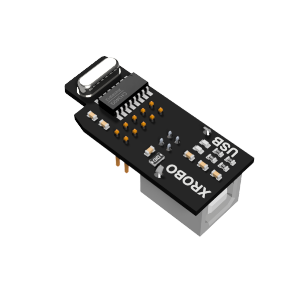
- ESSENTIAL when uploading code.
- It is utilized to upload programmed code to the CPU board.
- When you want to upload code to the CPU board, plug the download board into the download port on the CPU board.
- Input Voltage : 5V
Robot Structure Kit
Robot Structure Kit
Angle Connectors
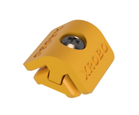
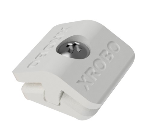
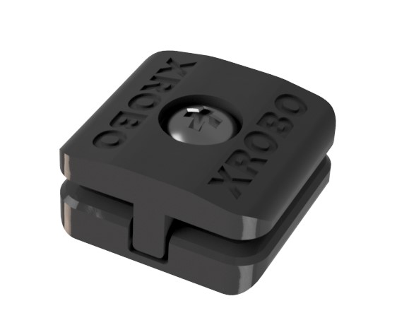
- Exclusive XROBO components designed to connect frames at specific angles, facilitating flexible robot assembly (Plate Connection Assembly, Patent No. 10-2111394).
- hese connectors can be easily assembled and disassembled by tightening and loosening bolts.
- Three types of angle connectors are available: 90 degrees, 135 degrees, and 180 degrees.
- Insert the frame into the slot at the end of the connector and tighten the bolt to secure the frame.
- To disassemble the robot, loosen the bolt to separate the connector and frame.
- Pre-assemble frames without tightening the bolts to quickly experiment with robot structures, reducing assembly mistakes.
Frames
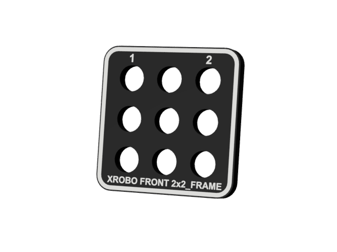
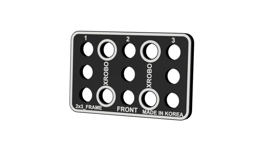
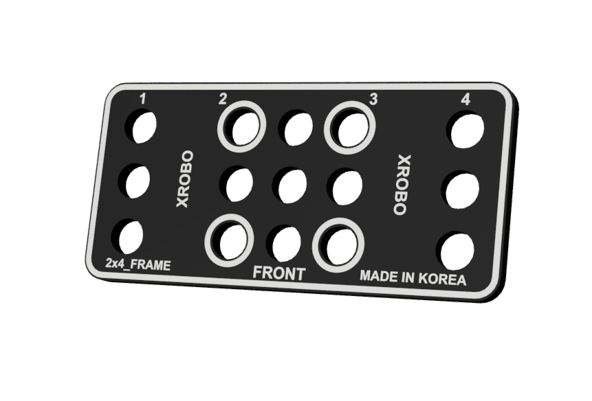
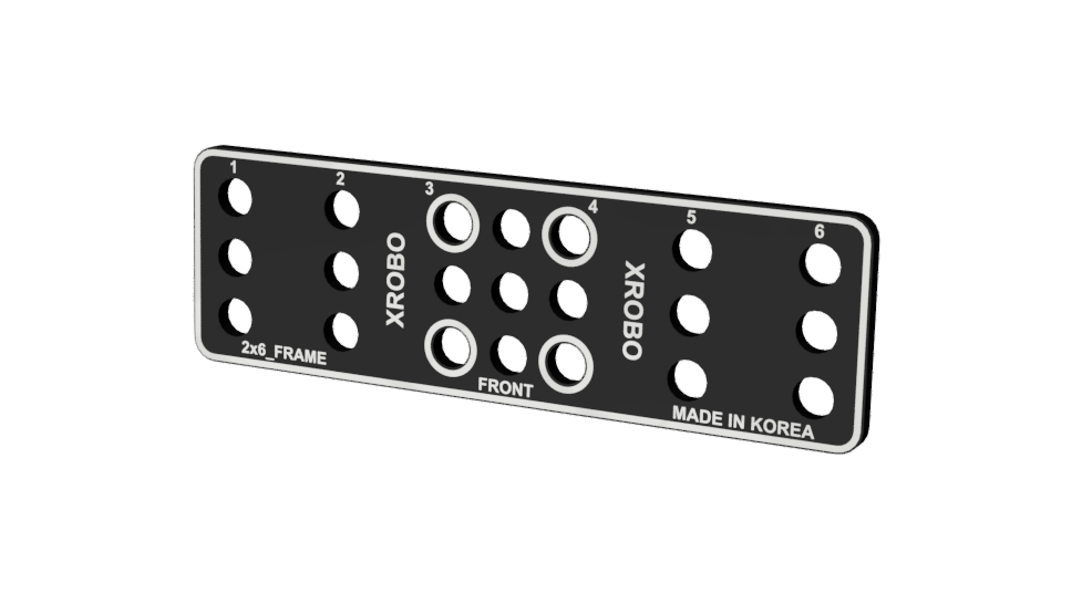
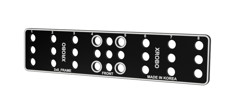
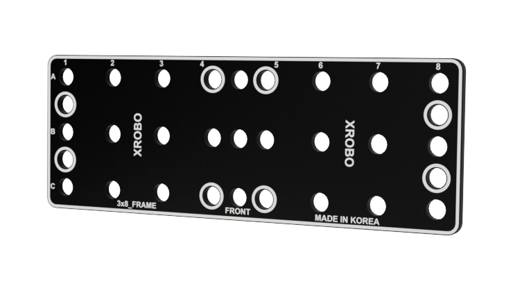
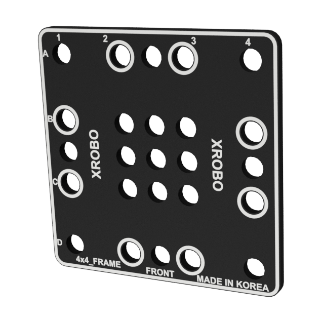
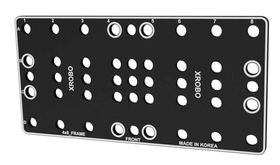
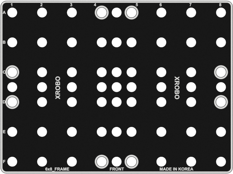
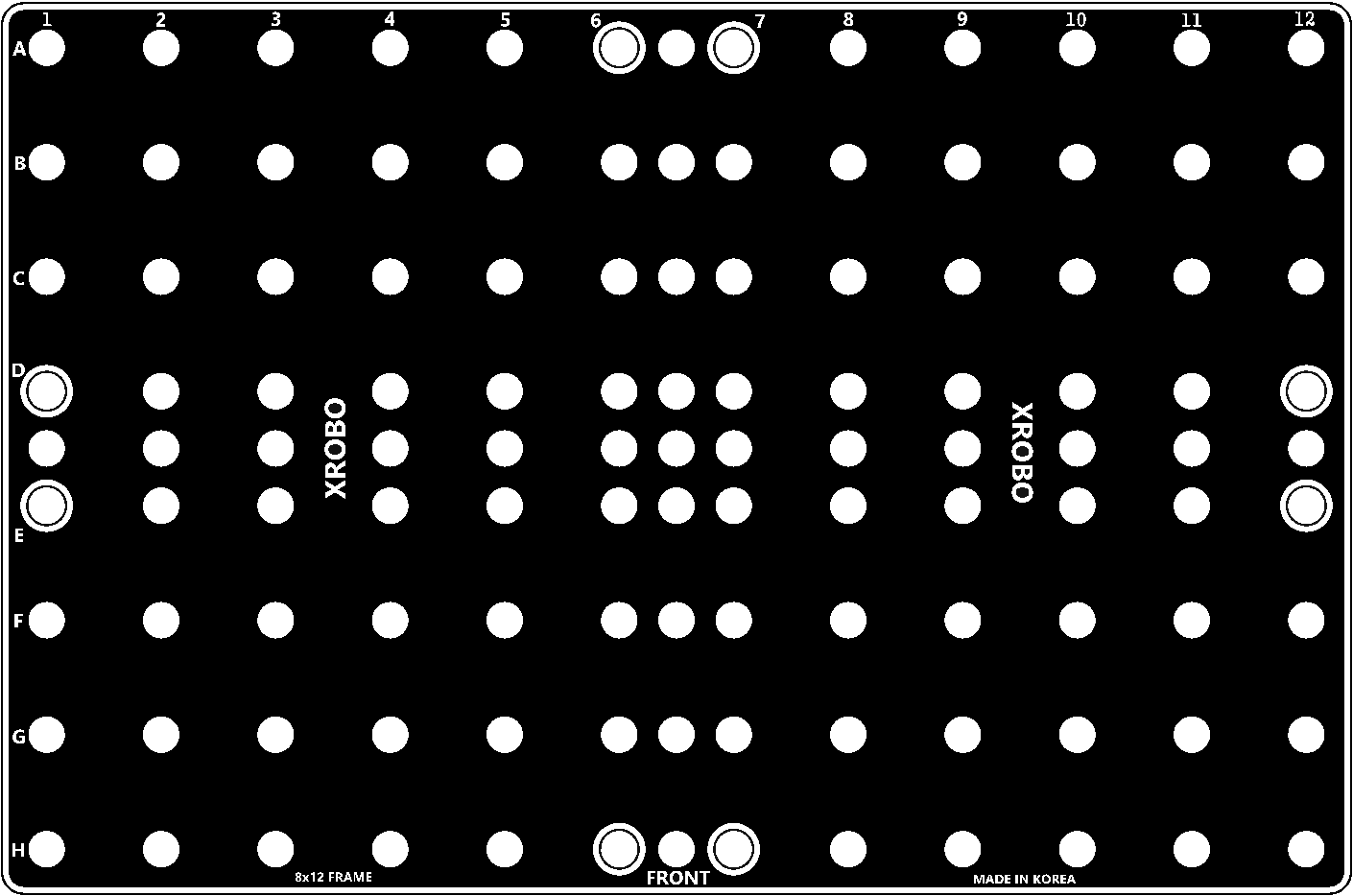
- Flat components that form the body of the robot.
- Frames can be quickly and easily connected using angle connectors to build the robot's structure.
- There are ten types of frames: 2x2F, 2x3F, 2x4F, 2x6F, 2x8F, 3x8F, 4x4F, 4x8F, 6x8F, and 8x12F.
- Insert the frame into the angle connector and tighten the bolt on the angle connector to secure the frame.
- To disassemble the robot, loosen the bolt on the angle connector to separate the frame.
- Pre-assemble the frames without tightening the bolts to quickly experiment with robot structures.
- Frequently used holes are marked with border lines to easily locate the assembly positions for the angle connectors.
Flexible Components
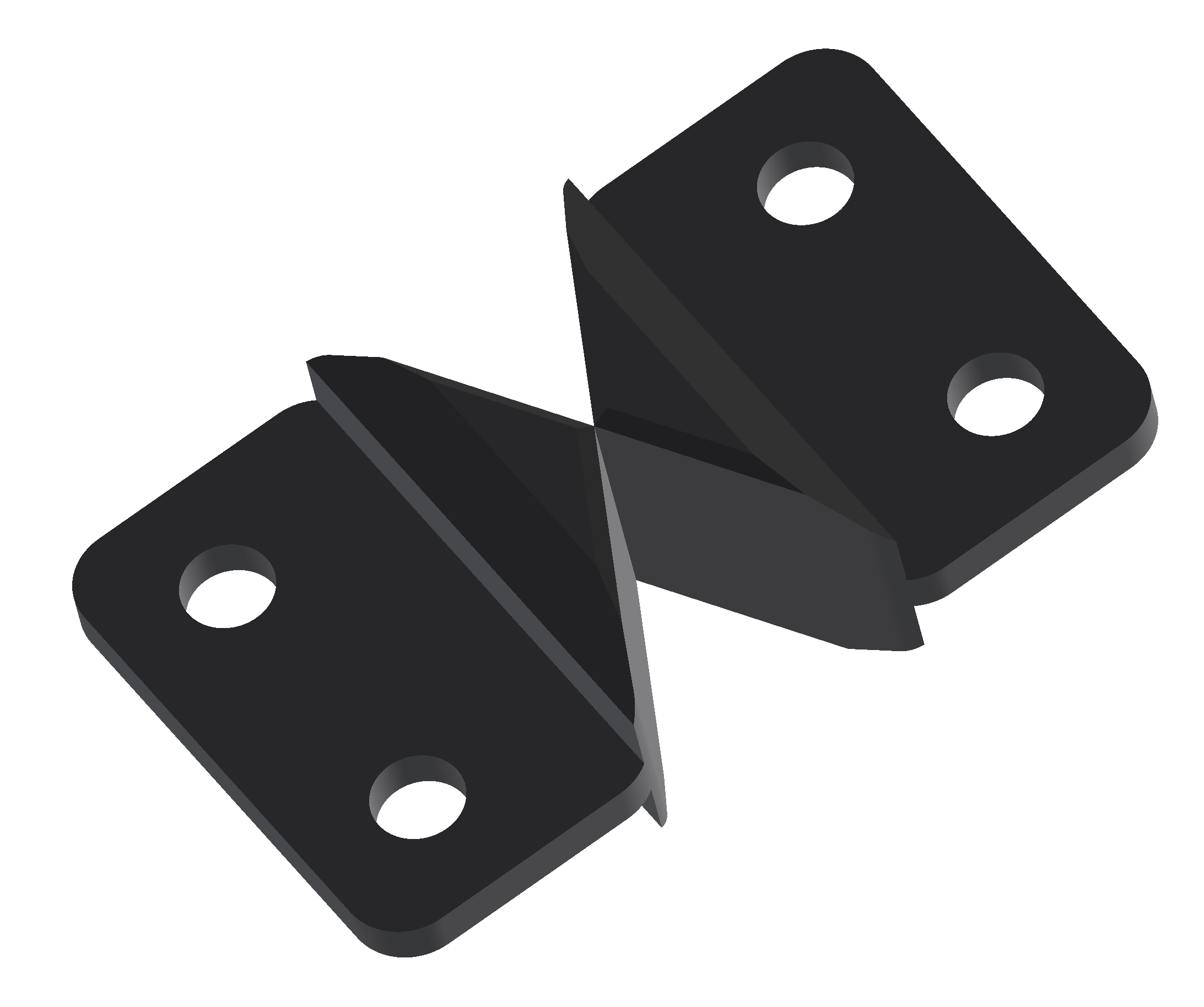
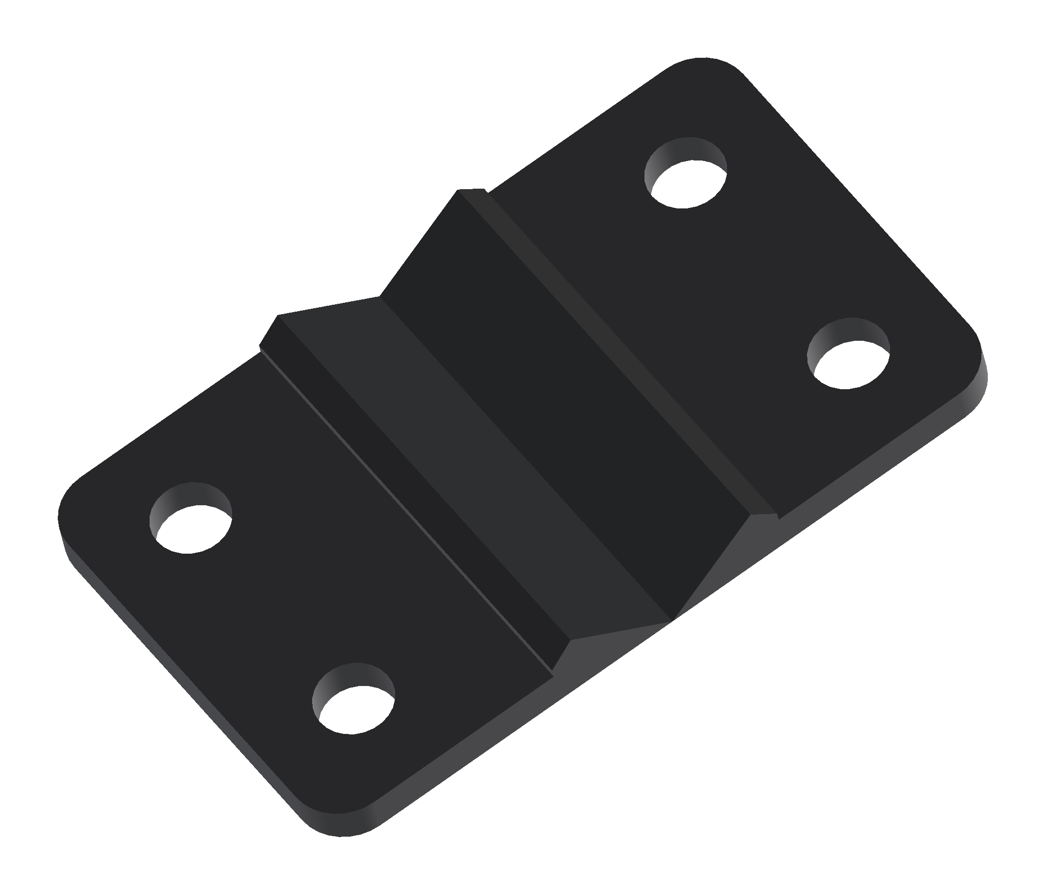
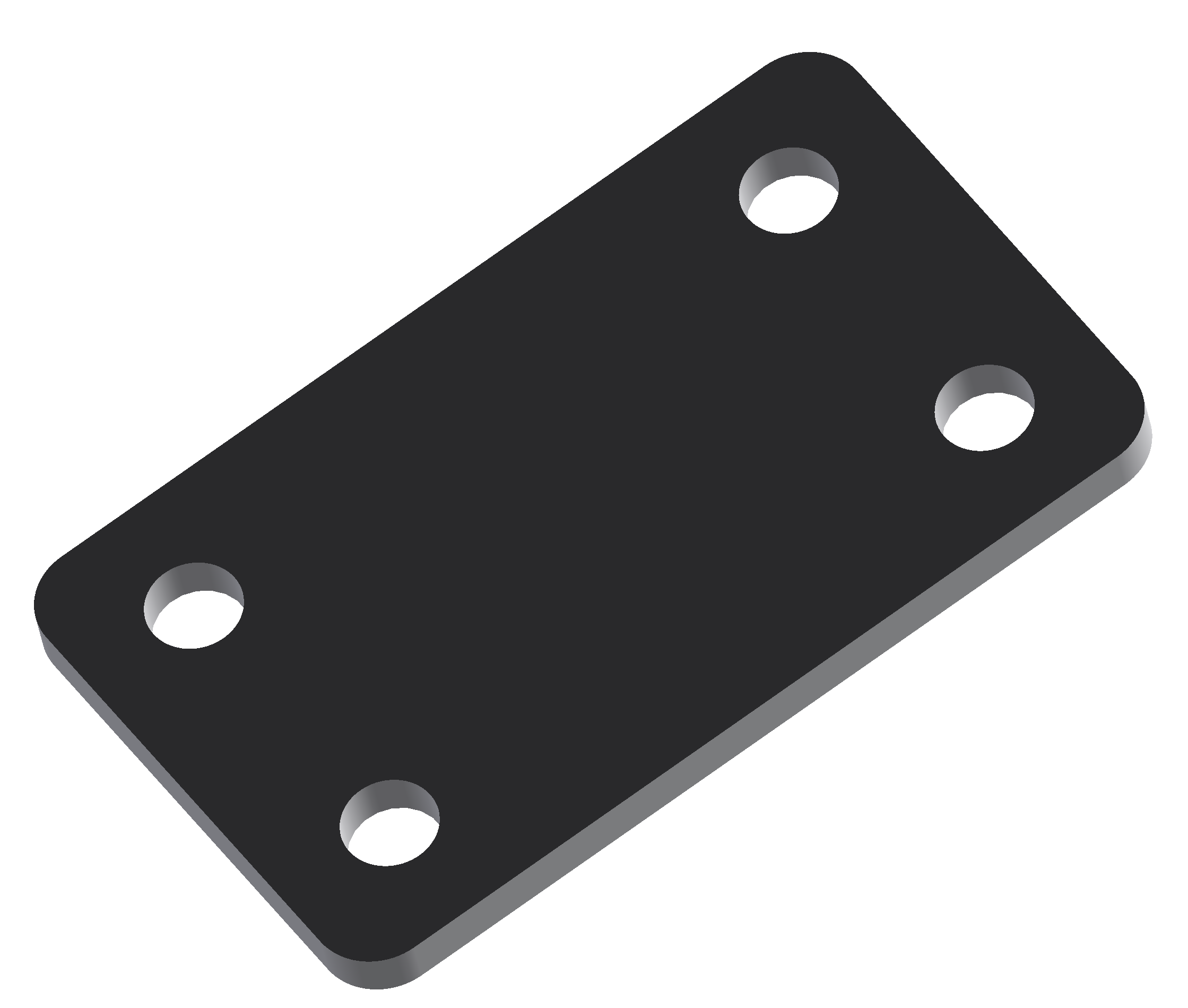
- Components used to create linkage structures.
- Using flexible components, realistic movements of objects can be implemented.
- There are three types of flexible components: left-right, up-down, and elastic.
- Insert both ends of the flexible component into the angle connectors, then tighten the bolts on the angle connectors to secure the flexible component.
- To disassemble the robot, loosen the bolts on the angle connectors to separate the flexible component.
Wheels
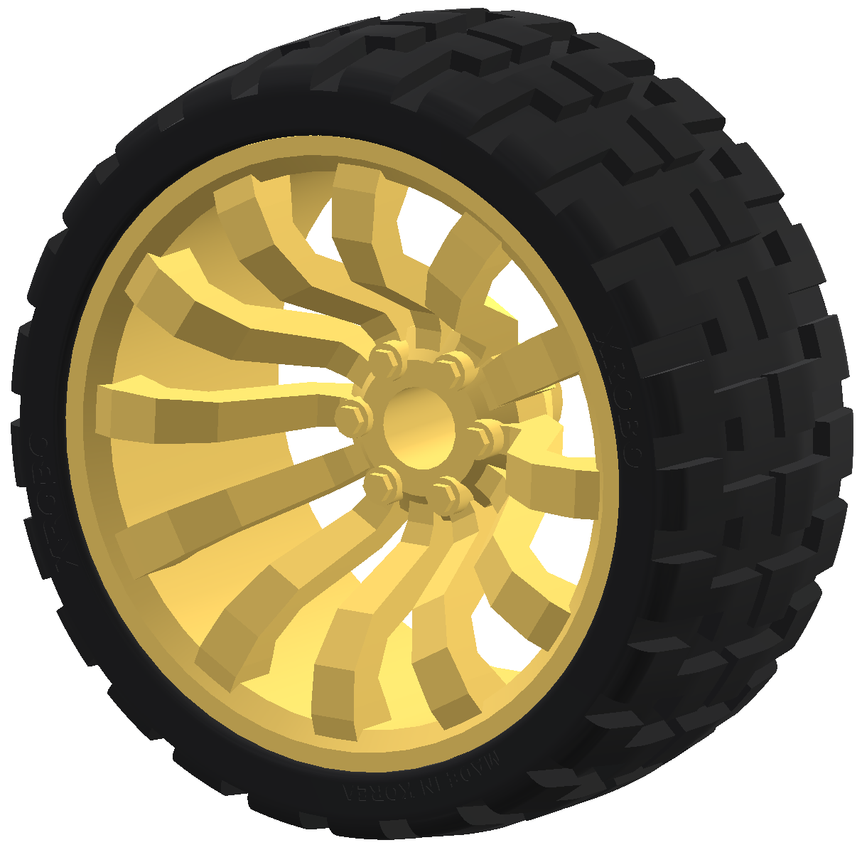
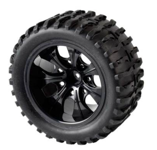
- Components used when building car-type robots.
- They are primarily connected to the shaft of a DC motor.
- There are two types of wheels: 82pi and 115pi.
- Attach the wheel to the shaft of the DC motor and secure it by tightening the bolt.
- Wheels can also be connected to supports for additional usage options.
Output Hardware
Output Hardware
LED Board
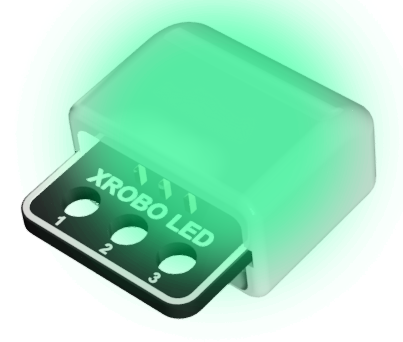
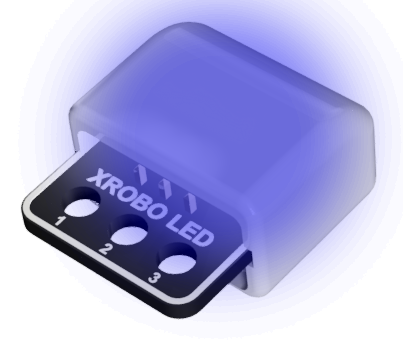
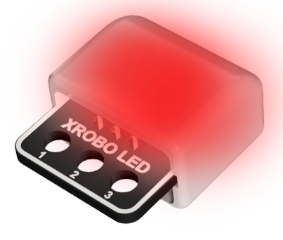
- Hardware used for emitting light.
- There are three colors of LEDs available: green, blue, and red.
- Connect a 3-pin cable to the pins on the back of the LED board.
- Connect the other end of the cable to an output port on the CPU board.
- Upload and run the code to control the LED.
- The color of the LED can be identified by the letter on the back of the board: G – Green, B – Blue, R – Red
- 3-pin Cable Sockets : 2
- Rated Voltage : 5V
- Input Voltage : 4~8V
- Colors : Green (G), Blue (B), Red (R)
DC Motor
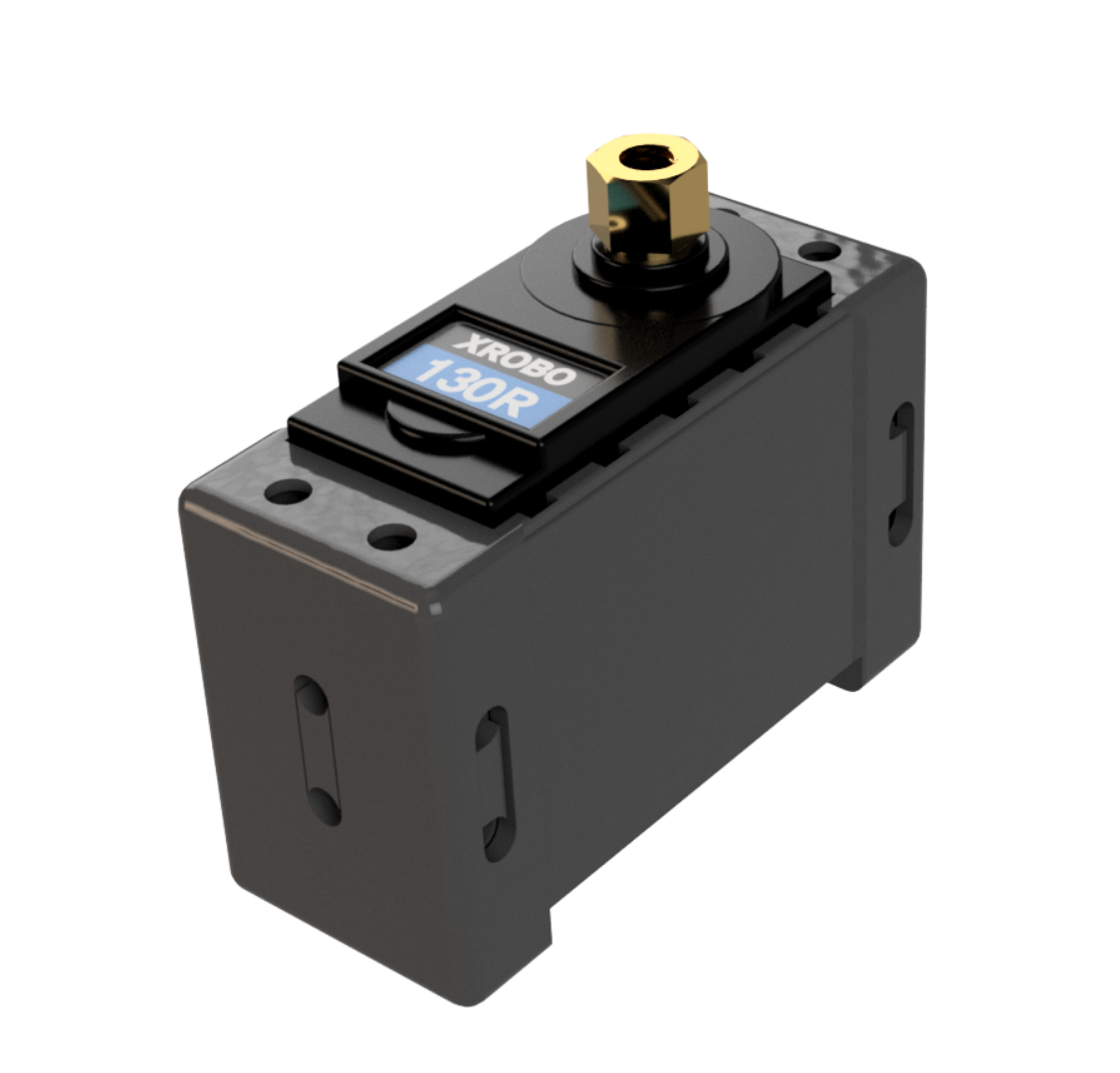
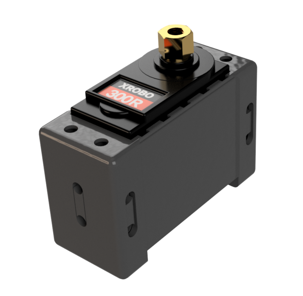
- ESSENTIAL when operating the DC motor.
- Hardware used for rotating components such as wheels.
- There are two types of DC motors: 130 RPM and 300 RPM, with the 300 RPM motor having a faster rotation speed.
- Attach a wheel or shaft guide to the motor shaft and tighten the bolt to create a rotational structure.
- Connect the DC motor to the frame using only bolts; no additional components are needed. The DC motor can be attached to the frame in various directions (Housing Assembly, Patent No. 10-2154670).
- Upload and run the code to control the DC motor.
130 RPM
- Voltage : 6~12V
- Maximum Current
- 6V – 800mA
- 12V – 1.2A
- RPM : 130 RPM
- Voltage : 6~12V
- Maximum Current
- 6V – 1A
- 12V – 1.5A
- RPM : 300 RPM
Servo Motor
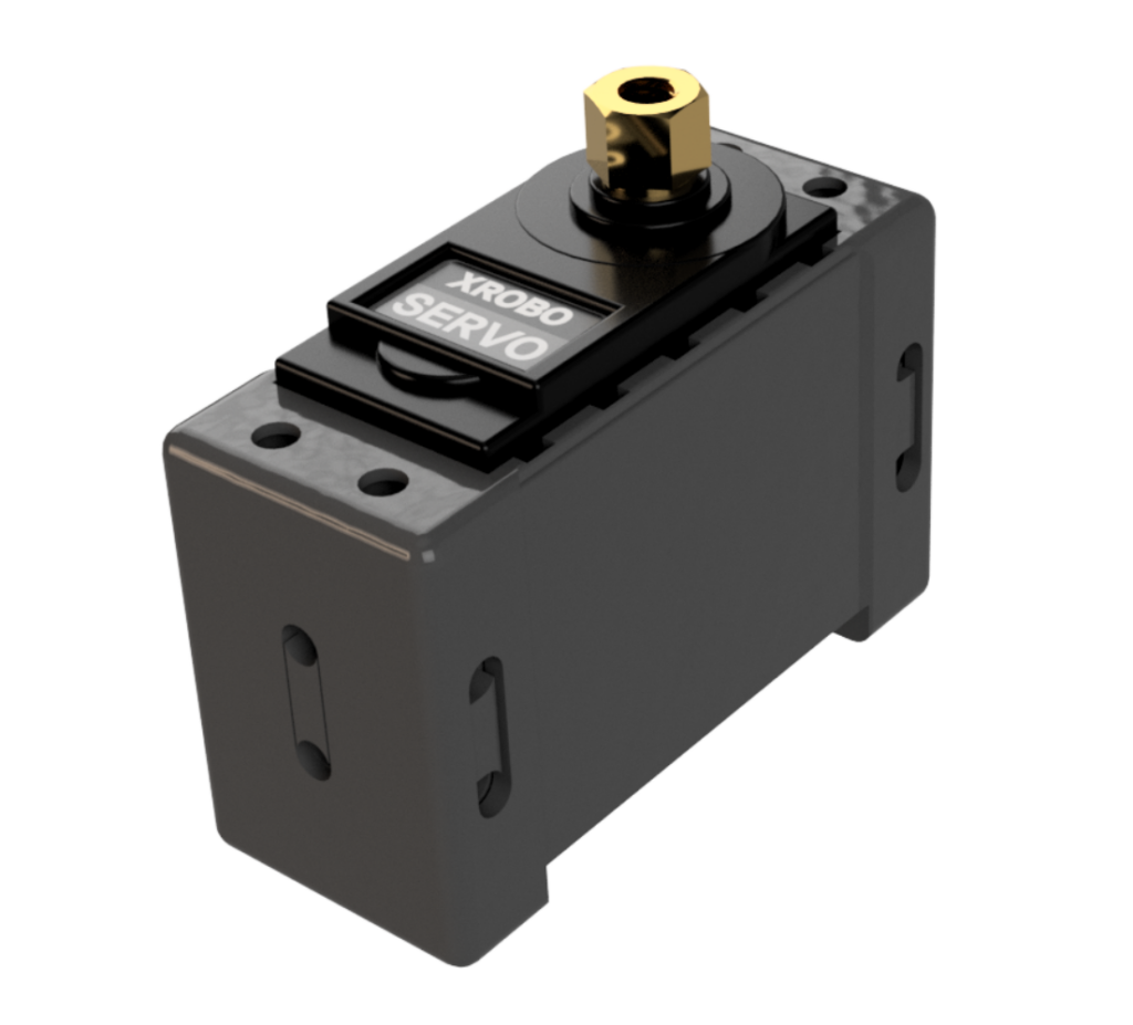
- Hardware used for rotating components to specific angles.
- It is primarily used in robot structures that require precise angle adjustments, such as lift structures and grab structures.
- Attach a shaft guide or similar component to the servo motor shaft and tighten the bolt to assemble.
- Typically assembled in a dual-shaft grab form, allowing strong and precise transmission of the motor’s power.
- Connect the servo motor to the frame using only bolts; no additional components are needed. The servo motor can be attached to the frame in various directions (Housing Assembly, Patent No. 10-2154670).
- Upload and run the code to control the servo motor.
- Voltage : 6V
- Speed : 50 RPM
- Torque : 5kg
- Maximum Current : 1A
- Angle : 1~270˚
FND Board
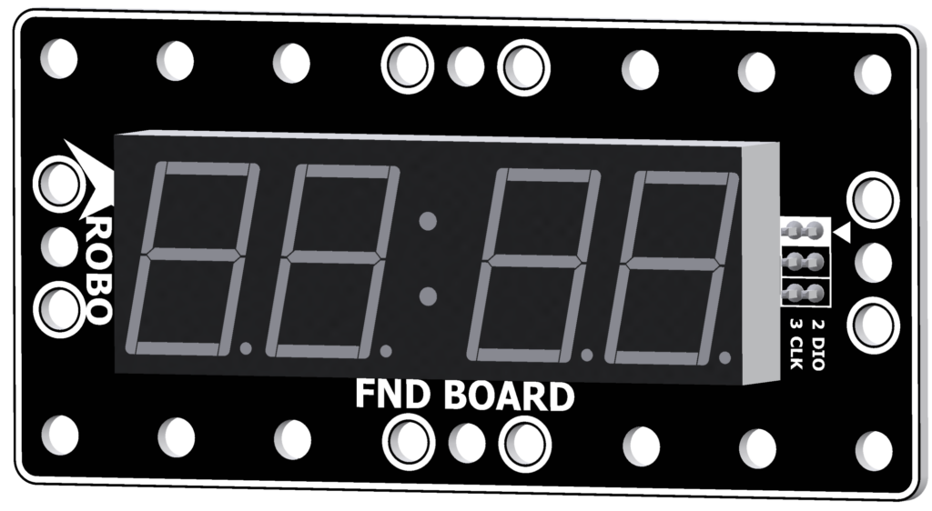
- The FND (Flexible Numeric Display) Board is an output hardware component used to display numbers with LEDs.
- It's also known as a 7-Segment display because it uses seven LEDs to represent each digit.
- It can display up to 4 digits and is commonly used to show time or scores.
- Connect a 3-pin cable to the ① CLK pin and another to the ② DIO pin on the back of the FND board.
- Connect the other end of each cable to the input ports on the CPU board.
- In [Operation Mode], connect the pins as follows: ① CLK pin to OUT5, ② DIO pin to OUT6.
- Upload the code to receive input on the FND board, ensuring that the cables are correctly mapped to their respective input ports.
- Voltage : 12V
- 3-pin Cable Sockets : 2
Dot Matrix Board
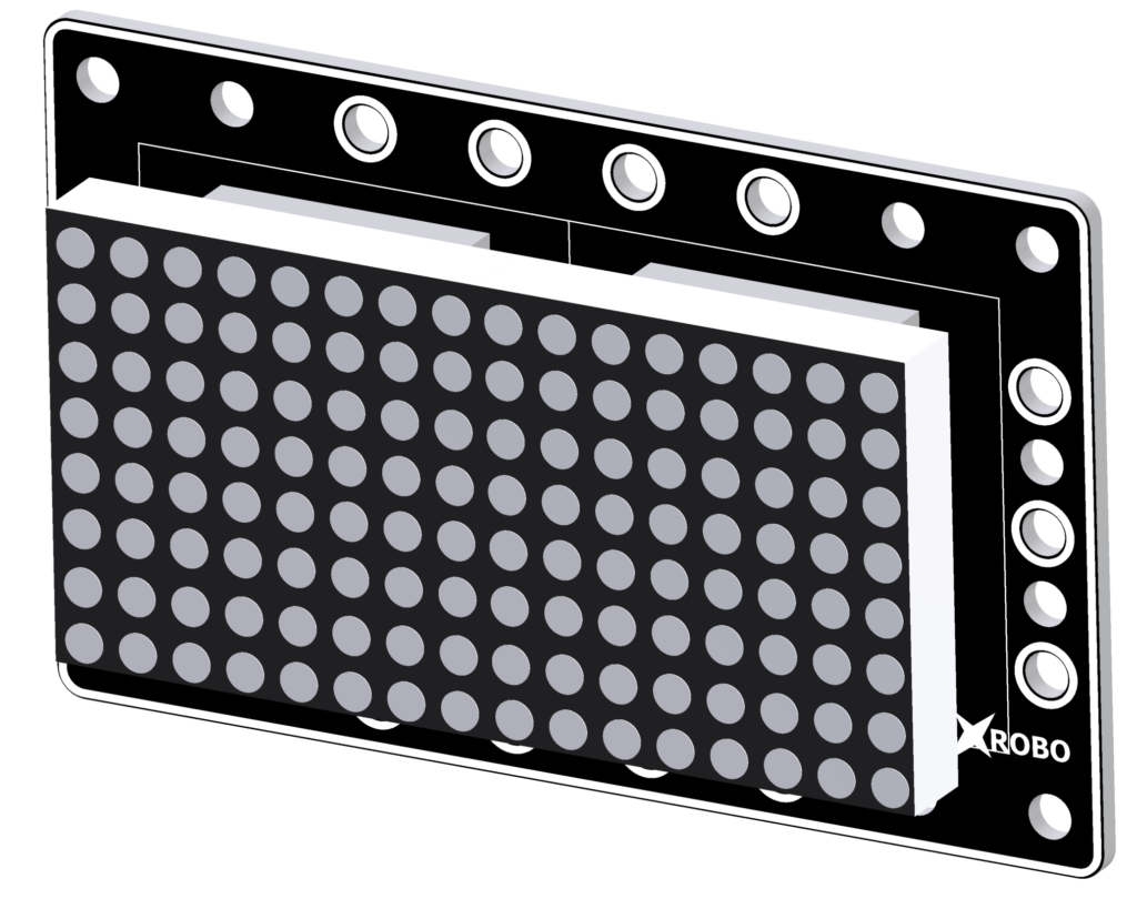
- The Dot Matrix Board is an output hardware component used to display numbers, letters, and images with small LED dots arranged in a regular pattern.
- It consists of two connected 8x8 matrices, allowing for a 16x8 LED display area.
- It is mainly used for text or game screens.
- Connect 3-pin cables to the ① LOAD pin, ② CLK pin, and ③ DIN pin on the back of the Dot Matrix board.
- Connect the other end of each cable to the input ports on the CPU board.
- In [Operation Mode], connect the pins as follows: ① LOAD pin to OUT2, ② CLK pin to OUT3, ③ DIN pin to OUT4.
- Upload the code to receive input on the Dot Matrix board, ensuring that the cables are correctly mapped to their respective input ports.
- Voltage : 12V
- 3-pin Cable Sockets : 8
Input Hardware
Input Hardware
RF Remote Control
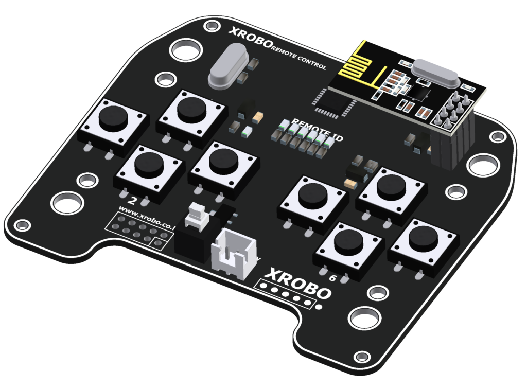
- The RF remote control requires an RF module to operate.
- This hardware is used for wirelessly controlling the robot.
- When a button is pressed, a Bluetooth signal is transmitted.
- Ensure that the RF module is plugged into the RF module port on the CPU board.
- Turn on the power to the remote control and press a button.
- If the RF module is plugged into the CPU board and the robot’s power is on, but the robot is not responding, check if the ‘Start’ block is correctly included in the code. If the problem persists, proceed with remote control pairing.
- MCU : ATmega328P
- Buttons : 8
- RF Module Socket : 1
- Voltage : 6V
X-Keypad
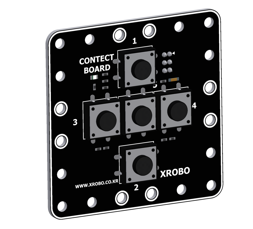
- The X-Keypad is hardware used for wired control of the robot.
- It features five numbered buttons.
- It is mainly used for building robots with buttons or for creating robots capable of unplugged coding.
- Connect a 3-pin cable to the pins on the back of the X-Keypad, and connect the other end of the cable to an input port on the CPU board.
- Upload the code to receive input from the X-Keypad and operate the robot.
- Buttons : 5개
- 3-pin Cable Sockets : 2
- Input Voltage : 5V
Contact Sensor
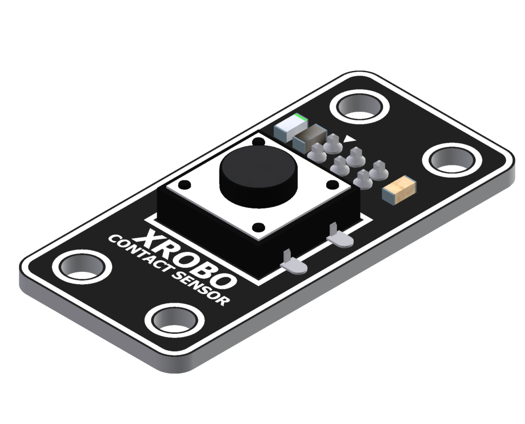
- The contact sensor is a hardware component used as a button.
- It features a single button and is primarily used for creating robots with button functionality.
- Connect a 3-pin cable to the pins on the back of the touch sensor, and connect the other end of the cable to an input port on the CPU board.
- Upload the code to receive input from the touch sensor and operate the robot.
- Buttons : 1개
- 3-pin Cable Sockets : 2
- Input Voltage : 5V
IR Sensor
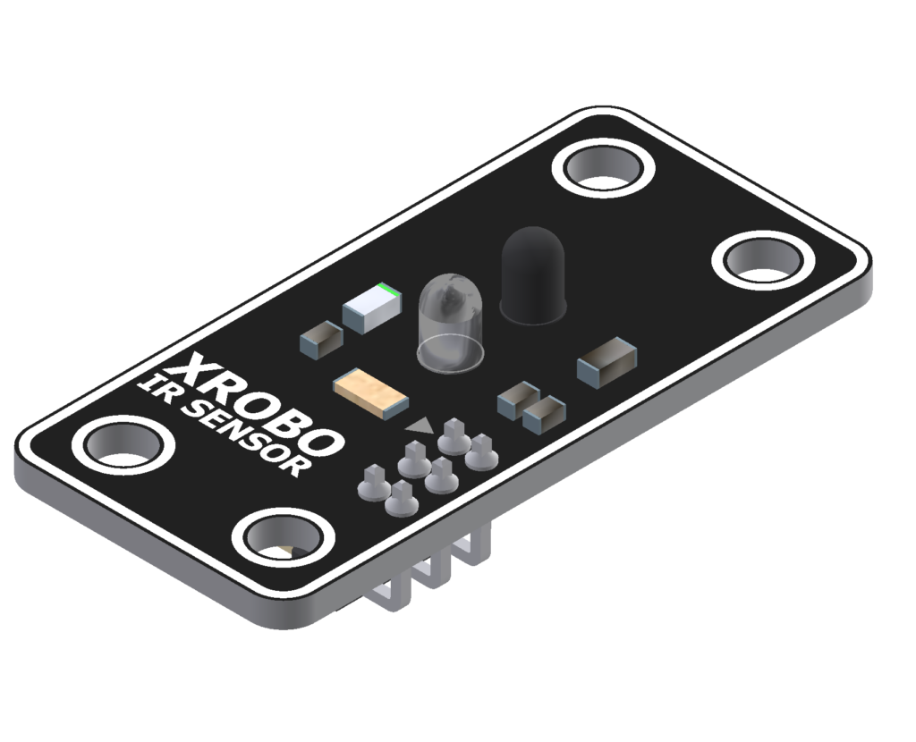
- The IR(infrared) sensor is used for detecting infrared signals.
- It is mainly used for measuring distances to objects or detecting light.
- Connect a 3-pin cable to the pins on the back of the infrared sensor, and connect the other end of the cable to an input port on the CPU board.
- Upload the code to receive input from the infrared sensor and operate the robot.
- 3-pin Cable Sockets : 2
- Input Voltage : 5V
Gyro Sensor
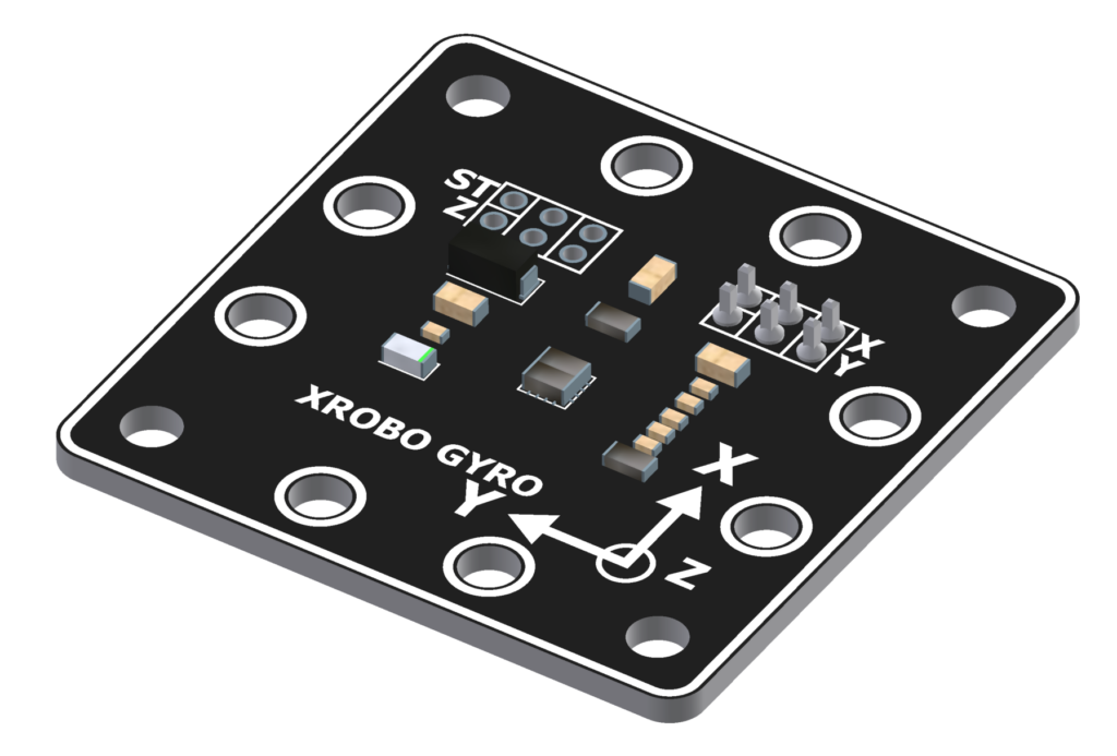
- The gyro sensor is used to detect the robot's rotational speed, tilt, and movements in various directions.
- It is commonly used in making wearable controllers.
- Connect 3-pin cables to the X pin and Y pin on the back of the gyro sensor.
- Connect the other end of each cable to the input ports on the CPU board.
- Upload the code to receive input from the gyro sensor, ensuring you correctly map the X and Y pins to the respective input ports.
- 3-pin Cable Sockets : 2
- Input Voltage : 5V
Sound Sensor
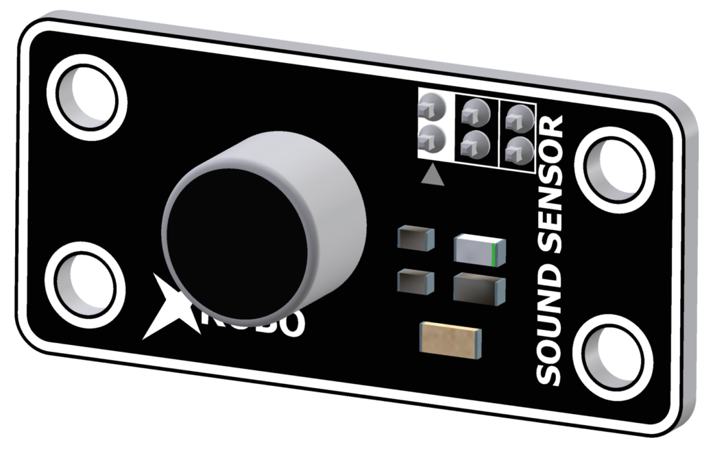
- The sound sensor is used to detect sound.
- It is used to sense ambient noise or to change the robot's actions based on the volume of the sound.
- Connect a 3-pin cable to the pin on the back of the sound sensor, and connect the other end to an input port on the CPU board.
- Upload the code to receive input from the sound sensor and operate the robot.
- Input Voltage : 5V
- 3-pin Cable Sockets : 2
CDS Sensor
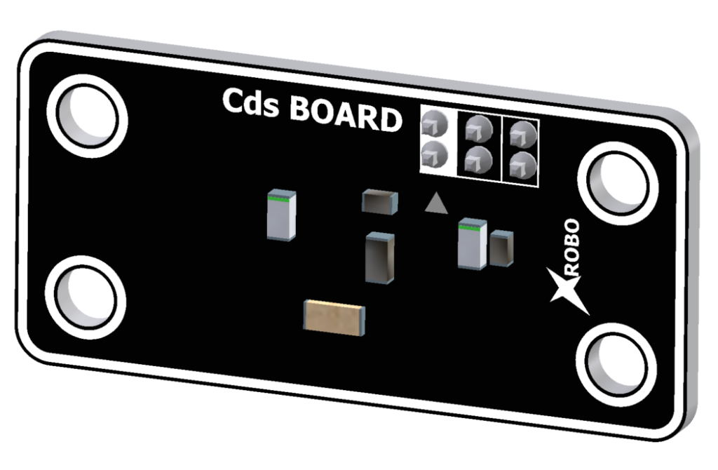
- The CDS sensor is used to detect light (visible light).
- It is used to sense ambient light or to change the robot's actions based on the light intensity.
- Connect a 3-pin cable to the pin on the back of the light sensor, and connect the other end to an input port on the CPU board.
- Upload the code to receive input from the light sensor and operate the robot.
- Input Voltage : 5V
- 3-pin Cable Sockets : 2
Joystick
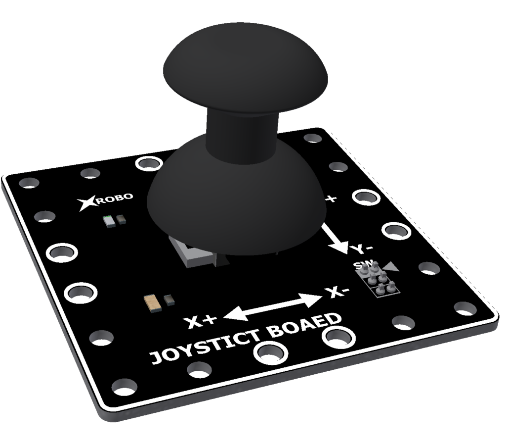
- The joystick is used to control the robot by moving the stick freely in all directions or pressing it down.
- Connect 3-pin cables to the ① X pin, ② Y pin, and ③ SW pin on the back of the joystick board.
- Connect the other end of each cable to the input ports on the CPU board.
- In [Operation Mode], connect the pins as follows:
- ① X pin to IN1 port
- ② Y pin to IN2 port
- ③ SW pin to IN3 port
- Upload the code to receive input from the joystick board, ensuring you correctly map the X, Y, and SW pins to the respective input ports.
- Input Voltage : 5V
- 3-pin Cable Sockets : 4
